At Molder’s World Inc. we take pride in being the developers and leading experts in Vortex® mold steel. We have developed industry standard guidelines and have compiled best tips and practices for the best results!
Vortex® Design Guidelines
When designing for Vortex® venting steel, the following guidelines should be considered.
Toughness
Due to limited physical toughness, Vortex® inserts are usually produced more than 1″ thick, so relief for proper venting can be npt holes machined then burned on the backside instead of mere EDM flat spots on the bottom.
Resins Used
Resins such as ABS, polypropylene, soft type PVC, polyethylene, acrylic, polyurethane, and styrene work very well with a 7-micron (.ooo3″) pore size. For low viscosity or talc-filled resins, it may be necessary to have an automated system reverse the airflow after each shot to purge the impurities from the pores. Rigid PVC resins will work, but only until the corrosive gasses close the pore. This can still be a feasible method if disposable inserts are used.
Size of Area to be Vented
Molder’s World, Inc.™ recommends that at least 10% of the cavity area be Vortex® to ensure proper venting. While this is not always possible, it is important to remember that the more square inches used in the cavity area, the lower the back pressure will be in the cavity. Due to the larger surface area, the insert will not require cleaning quite as often as a smaller piece. If Vortex® is used as a core or cavity half, instead of as an insert, there may not be a need for parting line vents.
Note: The thinner the Vortex® or the shorter the distance air has to travel to the exhaust line the better the venting will be. Keep in mind the physical properties of Vortex®.
Surface Finish Requirements
Since most applications can be addressed using inserted pieces on the core side, an EDM finish is accepted and will vent better than any other surface finish. Should an EDM finish be impractical the surface may be stoned or polished for a better finish after the EDM process. It is important to remember that if the venting steel is used on the cavity side of a mold, the gloss level will be severely reduced (from #9 to #3 with PP), so matching should be considered. If a low gloss level on a textured part is desired, it can be accomplished with Vortex®.
Slide/Lifter Applications
Vortex® can be used in slide or lifter applications. However, it is important to consider lubrication requirements on such a design. Lubricants will, in all likelihood, reduce or eliminate permeability in areas that coming into contact with Vortex®.
Vortex® Insert Installation

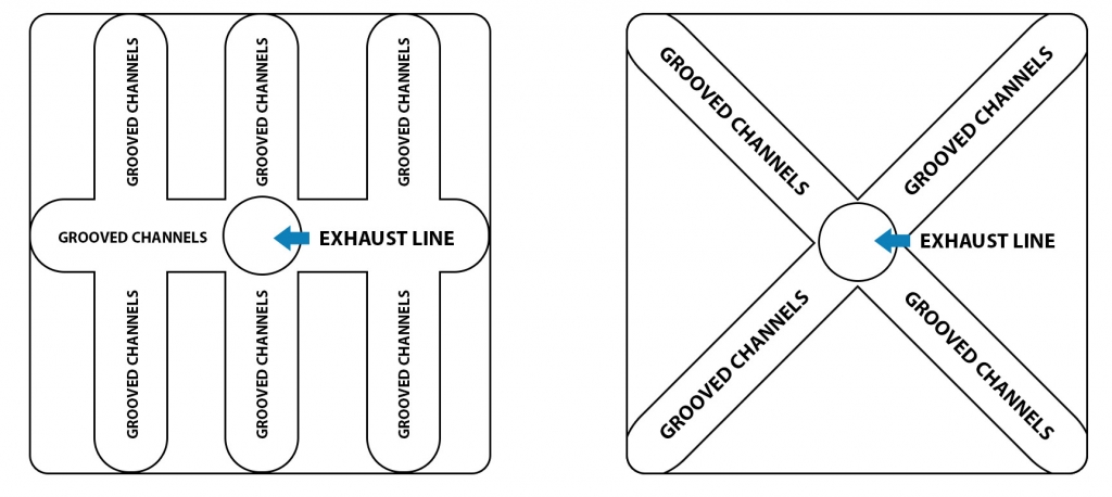
Various designs for the bottom of a Vortex® insert pocket

Vortex® Pin Installation
Best results can be achieved by drilling a vent hole into the bottom of the pin (See Below). This procedure considerably shortens the “escape route” for gas.

Since highest permeability can be achieved with an EDM finish, it is desirable to EDM the bottom and sides of the drilling hole for better efficiency. Be sure all EDM fluids are cleaned out before installing the pin into the tool.
Vortex® Insert Installation
VORTEX® INSERT WITH PROPER VENTING
-
In the above video, the bubbles throughout the lubricant show air passing through the Vortex® insert, simulating gas passing through in a mold
-
Proper EDM finishes on the surface, and at the bottom of the vent holes in the back of the Vortex® insert, are necessary for optimal results
-
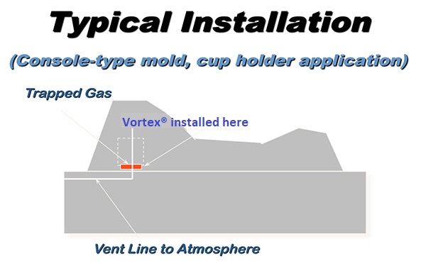
Ensure that there are proper vent lines from the back of the Vortex® insert to atmosphere so the gas can escape (See Vortex® Design Guidelines above)
Vortex® Success Tips
Proper Cleaning and certain designs work better than others.
For a quote on designing, building or cleaning Vortex® inserts please contact:
Molder’s World, Inc,
Phone: 513-469-6653 or Fax: 513-469-7212
MACHINING
Vortex® can be machined, but it should be machined wet to prevent work hardening. Because Vortex® is porous and will corrode, an oil-based coolant should be used if possible.
Finish machining should be done at a slower feed rate than other mold steels due to its tendency to chip or splinter as the tool exits the work piece “Picture framing” or machining the parameter of the insert first will also help in this matter.
The machining process will smear the pores closed on the surface of Vortex®. After machining the pores must be reopened by EDM.
Strategically placed high-pressure clean out or back flush/exhaust holes drilled & EDM machined into the Vortex® insert help to vent as well as assure proper cleaning.
EDM
Be sure to use multiple electrodes and to clean the electrode often while burning.
Max flush is critical.
Due to the nature of powder metal, particle debris in the cavity area will cause ``blow out`` in the steel, leaving pits.
During finish burning be sure to use low amperage (~4 amps).
An exhaust line through the core block must be adjacent to an EDM machined area on the side or back of the Vortex® insert. The cavity side of the Vortex® must also be EDM machined.
CLEANING
Vortex® must be cleaned both before it goes into production for the fist time to remove EDM cutting fluids and periodically (after 20,000-30,000 shots) during production to remove resin gas buildup.
Because of heath safety and fire risks it is recommended that Vortex® be professionally cleaned by Molder’s world, Inc. This is the only way to ensure renewed life for your Vortex® inserts.
OTHER IMPORTANT INFORMATION
The more square inches of Vortex® used in the cavity area the better the venting will be. The thinner the Vortex® or the shorter the distance the distance air has to travel to the exhaust line the better the venting will be. Keep in mind the physical limitations of Vortex®.
Mold releases such as silicon mold release will clog the surface pores of Vortex® if sprayed onto the material. Therefore positive air pressure should be blown back through the exhaust line while the tool is being sprayed. Inserts protected with mold saver must be cleaned before use unless BioCorr® is used.
Traditional welding of Vortex® is not recommend by Molder's World, Inc. due to its tendency to crack. It is best to re-machine the Vortex® insert and the weld or shim in the core pocket. Silver soldering or brazing is acceptable, however it is important to realize that where the material is soldered it will lose permeability. Laser welding/micro-welding with 400 series rod is also acceptable due to its low heat properties.
Texturing Vortex® is possible, however your texture house must be aware that they are working with Vortex® and if not familiar with the material they should contact Molder’s World Inc. immediately.
Be aware of your resins flash points. Vortex® has pores that average .0003″ in diameter.
Avoid running water lines through Vortex®, since they are difficult to seal and Vortex® will rust.
All technical and engineering data and suggested procedures, specifications and applications contained in this publication are for general information only. Molder’s World, Inc.™ and/or their distributors disclaim any and all express or implied warranties of merchantability, suitability for any particular or use, or freedom from infringement of any patent, trademark or copyright. Vortex® and Porcerax II® are registered trademarks of Molder’s World, Inc.™
Speaker Grill Best Practices
Where to buy:
Vortex® should be purchased from a licensed Vortex® distributor for traceability and warranty concerns.
All Vortex® should be purchased from licensed distributor for warranty and counterfeit steel concerns. Molder’s World, Inc. is currently the exclusive Vortex® distributor world-wide.
Vortex® Speaker Grill Best Practices:
Minimum surface area
Molder’s World, Inc. recommends that the entire area where the hole pin shut offs make audio holes in the grill to be Vortex®. The outer round or oval sound rib is the best place to split the parting line between the Vortex® core insert and the P20 core.
Minimum Thickness
Molder’s World, Inc. recommends that for speaker grill inserts
6” OD and under to be a minimum 1-5/8” thick at the thinnest cross section. Inserts over 6” OD should be at least 2-1/8” thick at the thinnest cross section.
Shut off hole pin height
If the design calls for a split pin configuration, then the height of the Vortex® pin should not be more than 40% of the depth of the hole. 30% is better. The Vortex® pins should also be larger in diameter to assure alignment with no flash. Any pin that is lees than 80% of a full diameter should be eliminated or made into a “dummy pin” with no shut off pressure from the cavity side, due to toughness.
Vortex® part surface machining
Vortex® machines like a 40 HRc 400 series stainless steel. It should be machined with coolant to prevent work hardening. This water soluble coolant does need to be cleaned after the insert is complete. (See cleaning)
The insert should be CNC machined on the part molding surface with enough stock (.010 – .015”) to then be EDM burned to open the pores that will be closed by the machining process. The lower the amperage used the better the finish will be. Do not blast the surface with any media to attempt a better finish. This includes AQR or talc media. EDM low amperage finish will be better and will not close the pores.
Inserts with standing shut off pins that mold the holes in the grill should be burned with at least 2 electrodes. One for roughing & one for finish orbiting work. This will provide better part release. For inserts that have a web thickness less than .7mm between the pins, three electrodes may be needed. Two for roughing the pins and one for finish orbit.
Cooling Vortex® inserts
Molder’s World, Inc. does not recommend running water through the Vortex® insert due to the nature of the material being porous & the difficulty in sealing the water line pores. A cooling plate bolted to the bottom of the Vortex® insert works well.
Draft angles
Draft angles for the shut off pins and the rib area should be as generous as possible due to the nature of an EDM burned sintered metal like Vortex® and its rougher than P20 surface.
Rib sidewall areas may need to be stoned to remove EDM slag. Rib areas may also be milled if filling of the ribs is not an issue. Pins should always be EDM burned however. If the ribs are milled and filling the rib area becomes an issue, an electrode should then be made to burn the bottoms of the rib areas.
Grill mesh thickness
In general, the smaller the web or mesh thickness, the higher the melt temperature needs to be to push the plastic between the shut off pins to fill the grill, creating an exaggerated shrink situation that grips the shut off pins, hindering release. This, along with the tendency to over pack the part in order to fill it, creates poor release.
Molder’s World, Inc. recommends at least .7mm thick mesh to avoid the above problems.
Outside taper on the inserts
The outside of the Vortex® insert should not be tapered. It is acceptable to relieve the OD below the parting line, but if the OD is tapered, then repairing a damaged insert by lowering the surface by 1/8” to 1⁄4” is not possible. Lowering the surface is sometimes the best way to repair the molding surface when damaged. (See repairs)
Rib Design
Because of plastic shrinkage, it is best to put .015” to .020” rads on the 6 vertical corners of the hexagon bosses that mold the rib pattern. This will aid in release.

Part Ejection
It is not necessary to have ejector pins through the Vortex® insert for part release, but it is possible to do that without damaging the Vortex® insert. Lifters that slide up the outside diameter of the insert and lift on the outer ring of the speaker grill work well.
Venting Design
Venting the Core Block
It is necessary to have a drilled exhaust line through the core block pocket to atmosphere. This drilled hole should line up with the drilled and EDM burned center vent hole on the backside of the Vortex® insert.

Venting the backside of the Vortex® core insert
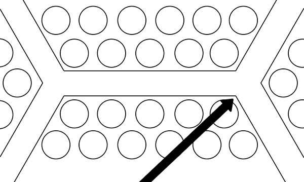
In order to get optimum venting through the Vortex® insert,a series of drilled & EDM burned flat, 3/8” NPT blind holes need to be machined on the backside of the insert. By using NPT holes the insert can be pressurized & back flushed during cleaning. Molder’s World, Inc. recommends a minimum of 6 holes in a bolt hole pattern with an extra 7th hole in the center of the insert. (See Right) These holes should be within 5/8” to 3⁄4” of the molding surface and connected to the center hole by mill grooving the bottom of the insert or grooving the bottom of the pocket in a wagon wheel pattern.

Cleaning Vortex® inserts:
Heating Vortex® to a temperature over 500°F will only cook the contaminants inside making it harder to clean and will make the surface of the material brittle.
A professional that has Vortex® cleaning experience as well as explosion proof ultrasonic cleaning equipment should ALWAYS clean Vortex® inserts. Molder’s World, Inc. provides that service.


